Bargraph / instruments #I
Command group to show bar graphs, sliders and rotary / pointer instruments |
|

Bargraph
Place rectangular Bargraph (Instrument Bar Rectangle) |
Obj-ID, DrawStyle-Filling, DrawStyle-Background, x, y, Anchor, Width, Height, Radius(0), StartValue(0), EndValue(100), Direction (1), Angle(0) |
|
Place triangular Bargraph (Instrument Bar Triangle) |
Obj-ID, DrawStyle-Filling, DrawStyle-Background, x, y, Anchor, Width, Height, Tip(0), StartValue(0), EndValue(100), Direction(1), Angle(0) |
|
Place curved Bargraph (Instrument Bar Arc) |
Obj-ID, DrawStyle-Filling, DrawStyle-Background, x, y, Anchor, Radius, Thickness, StartAngle, EndAngle, StartValue(0), EndValue(100), Direction (1) |
Slider
Define Slider along path (Instrument Group Slider) |
Group-ID, Path-ID, Controller-ID, Tangential(0), StartValue(0), EndValue(100) |
Rotary / pointer instruments
Define pointer instrument from objects (Instrument Group Meter) |
Group-ID, Indicator-ID, StartAngle, DeltaAngle, StartValue(0), EndValue(100) |
|
Place a instrument from the eDIP series (Instrument Picture Place) |
Object-ID, 'InstrumentName'; x, y, Anchor, Width(0), Height(0), StartValue(0), EndValue(100), Angle(0) |
Setting Bargraph / instrument
Set value of Bargraph/Instrument (Instrument Value Set) |
Obj-ID, Value, Time(0), ActionCurve-No.(0) |
|
Change Start-/End-value of a Bargraph/Instrument (Instrument Value New) |
Obj-ID, StartValue, EndValue(no change) |
|
Set Bargraph/Instrument value to calculation value with AutoUpdate (Instrument Value Autochange) |
Obj-ID, (Calculation), Time(0), ActionCurve-No.(0) |
|
Change Bargraph/Instrument calculation for AutoUpdate (Instrument Value Calulation) |
Obj-ID, (Calculation) |
Bargraph
Bargraphs can be used for displaying or for entering values. After the definition (#IBR, #IBT, #IBA), the Bargraph can neither be operated by touch nor does it display a predefined value. To activate it for touch input, you need the command #TID. Values can be set with the #IVS command. The #IVA function is required if the Bargraph should change automatically when changing a calculation value (e.g. analog input, register value, ...). In the following example, a rectangular Bargraph is placed, pre-assigned to the value 30 and activated by touch.
|
... #IBR 1,2,1,20,20,7,150,30,10 #IVS 1,30 #TID 1,1 ... |
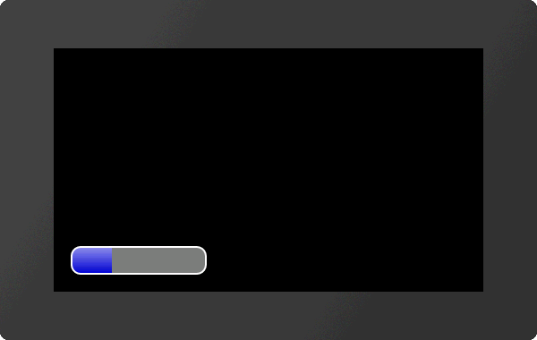
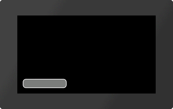
#IBR |
Obj-ID, DrawStyle-Filling, DrawStyle-Background, x, y, Anchor, Width, Height, Radius(0), StartValue(0), EndValue(100), Direction (1), Angle(0) |
The command places a rectangular Bargraph with the Anchor, Width and Height at the position x, y. The filling color is taken from the DrawStyle-Filling. The DrawStyle-Background specifies the background and frame color. The structure of the DrawStyle sub-chapter is explained in more detail. A Radius can optionally be specified. This rounds off the corners. The StartValue and EndValue determine the two limits of the Bargraph. The running direction is determined by Direction:
Direction |
|
0 |
Right to left |
1 |
Left to right |
Rotation around the anchor (Angle) can also be set.
|
... #IBR 1,2,1,20,20,7,150,30,10 ... |
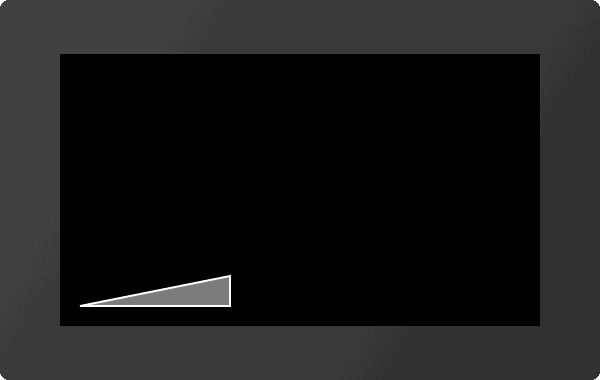
#IBT |
Obj-ID, DrawStyle-Filling, DrawStyle-Background, x, y, Anchor, Width, Height, Tip(0), StartValue(0), EndValue(100), Direction(1), Angle(0) |
The command places a triangular Bargraph with the Anchor, Width and Height at the position x, y. The filling color is taken from the DrawStyle-Filling. The DrawStyle-Background specifies the background and frame color. The structure of the DrawStyle sub-chapter is explained in more detail. The tip is on the left side. The optional parameter Tip specifies the position of the tip:
Tip |
|
0 |
Bottom |
1 |
Top |
2 |
Middle |
StartValue and EndValue determine the two limits of the Bargraph. The running direction is determined by Direction:
Direction |
|
0 |
Towards tip |
1 |
Away from tip |
Rotation around the anchor (Angle) can also be set.
|
... #IBT 1,2,1,20,20,7,150,30 ... |
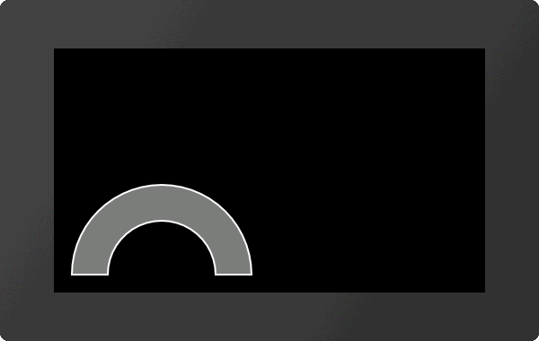
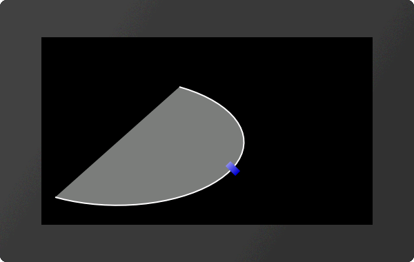
#IBA |
Obj-ID, DrawStyle-Filling, DrawStyle-Background, x, y, Anchor, Radius, Thickness, StartAngle, EndAngle, StartValue(0), EndValue(100), Direction (1) |
The command places a curved Bargraph with the Anchor and given Thickness at the position x, y. The size is determined by the parameters Radius, StartAngle and EndAngle. The filling color is taken from the DrawStyle-Filling. The DrawStyle-Background specifies the background and frame color. The structure of the DrawStyle sub-chapter is explained in more detail. The StartValue and EndValue determine the two limits of the Bargraph. The running direction is determined by Direction:
Direction |
|
0 |
Counterclockwise |
1 |
Clockwise |
Rotation around the anchor (Angle) can also be set.
|
... #IBA 1,2,1,20,20,7,100,40,0,180 ... |
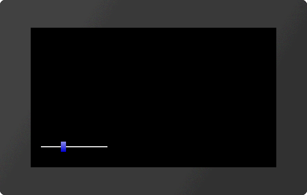
Slider
A slider consists of a path (#GPL, #GPP) and a knob (e.g. #GRR, #PPP, ...). Both objects have to be defined in advance and grouped together (#OGA). The start position of the controller (value 0) coincides with the construction point of the path. Nevertheless, it makes sense to position the controller in the right place, since the group limitation (bounding box) does not adapt automatically.
To activate the slider for touch input, you need the command #TID. Values can be set with the #IVS command.
|
... #GPL 1,1,20,40,150,40 #GRR 2,2,20,40,4,10,20 #OGA 3,1,2 #IGS 3,1,2 #IVS 3,30 #TID 1,3 ... |
|
... #GPP 1,1,20,40,?E0,100,50,0,200,200 #GRR 2,2,20,40,4,10,20 #OGA 3,1,2 #IGS 3,1,2,1 #IVS 3,60 #TID 1,3 ... |
#IGS |
Group-ID, Path-ID, Controller-ID, Tangential(0), StartValue(0), EndValue(100) |
The command converts an existing group Group-ID into a slider. The group must contain at least two existing objects:
The controller moves along the path:
Tangential |
|
0 |
Controller does not turn |
1 |
Controller rotates tangentially to the path |
StartValue and EndValue determine the two limits of the slider.
Rotary / pointer instruments
A rotary / pointer instrument consists of a background (scale) and a pointer. Both objects have to be defined in advance and grouped together (#OGA). When designing the pointer, make sure that it is positioned in the zero position of the scale. To activate the instrument for touch inputs, the command #TID is required. Values can be set with the #IVS command. With the help of the Meter Editor instruments can be easily created.
|
... #PPP 1,<P:picture/Voltmeter.evg>,20,20,7,150,150,0 #PPP 2,<P:picture/Voltmeter_Needle.evg>,66,91,5,6,100,70 #OAO 3,20,2 #OAA 0,2 #OGA 3,1,2 #IGM 3,2,160,-140,0,100 #IVS 3,60 #TID 1,3 ... |
|
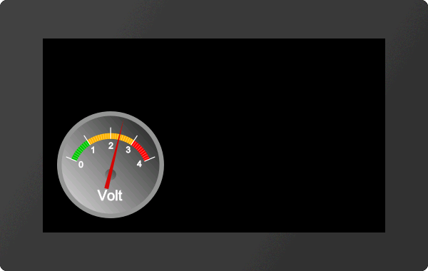
Alternatively, instruments from the eDIP series can also be placed directly (see #IPP)
Define pointer instrument from objects
#IGM |
Group-ID, Indicator-ID, StartAngle, DeltaAngle, StartValue(0), EndValue(100) |
The command converts an existing group Group-ID into a pointer instrument. The parameter Indicator-ID determines the pointer. The pointer must be positioned in a way that it points to the value 0. The StartAngle parameter specifies the start angle of the scale. The DeltaAngle determines the direction of rotation (positive: counterclockwise; negative: clockwise) and the total angle of rotation (from the start angle). Optionally, the start and end values (input and output values) can also be specified.
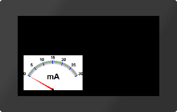
Place a instrument from the eDIP series
#IPP |
Object-ID, 'InstrumentName'; x, y, Anchor, Width(0), Height(0), StartValue(0), EndValue(100), Angle(0) |
This command is available for compatibility reasons. Finished instruments from the eDIP series, which were created with the LCDTools, can be displayed directly. The instrument must be converted to the * .epi format beforehand using EAconvert.exe. The size is determined by the parameters Width and Height. If width = 0 and height = 0, the original size of the instrument is adopted. If only one of the two parameters is 0, the instrument is adjusted proportionally. Optionally, the start and end values (input and output values) and the rotation around the anchor (Angle) can be specified.
|
... #IPP 1,<P:instrument/instrument.epi>,20,20,7,200 ... |
... #IPP 1,"instrument";20,20,7,200 ... |
Setting Bargraph/Instrument
Set value of Bargraph/Instrument
#IVS |
Obj-ID, Value, Time(0), ActionCurve-No.(0) |
With the command, a bar graph or instrument is set to a new Value. The Time parameter is specified in 1/100s. If the value is positive, the time period is used for the total deflection, meaning a constant speed. A negative value determines the time until the new value is reached. The speed is depending on the distance. The ActionCurve-No. determines the chronological sequence. This is explained in more detail in the subchapter Action Curves and Action Paths.
Change Start-/End-value of a Bargraph/Instrument (from V1.1)
#IVN |
Obj-ID, StartValue, EndValue(no change) |
The command assigns a new start and / or end value to the Bargraph or instrument.
Set Bargraph/Instrument value to a calculation with AutoUpdate
#IVA |
Obj-ID, (Calculation), Time(0), ActionCurve-No.(0) |
The value of a Bargraph or instrument is automatically calculated using the Calculation (e.g. analog input, register, calculation) and always changed when its value changes. The Time parameter is specified in 1/100s. If the value is positive, the time period is used for the total deflection, meaning a constant speed. A negative value determines the time until the new value is reached. The speed is depending on the distance. The ActionCurve-No. determines the chronological sequence. This is explained in more detail in the subchapter Action Curves and Action Paths.
Change Bargraph/Instrument calculation for AutoUpdate
#IVC |
Obj-ID, (Calculation) |
The command changes the Calculation for the AutoUpdate function. Now the value of the Bargraph / instrument is updated whenever the new calculation value changes. However, the old calculation (#IVA) is used for display value.