Draw / graphic primitives #G
Command group to show graphical simple objects: |
|

Place rectangle (Graphic Rounded Rectangle) |
Obj-ID, DrawStyle-No, x, y, Anchor, Width, Height(=Width), Radius (0), FrameThickness(0), Angle(0) |
|
Place regular polygon (Graphic Geometric Polygon) |
Obj-ID, DrawStyle-No, x, y, Anchor, Radius, Corners, FrameThickness(0), Angle(0) |
|
Place star (Graphic Geometric Star) |
Obj-ID, DrawStyle-No, x, y, Anchor, Radius1, Radius2, Tip, FrameThickness(0), Angle(0) |
|
Place circle/ellipse (Graphic Ellipse Total) |
Obj-ID, DrawStyle-No, x, y, Anchor, RadiusX, RadiusY(=RadiusX), FrameThickness(0), Angle(0) |
|
Place circular sector/piece of cake Graphic Ellipse Pie) |
Obj-ID, DrawStyle-No, x, y, Anchor, RadiusX, RadiusY, StartAngle, EndAngle, Angle(0) |
|
Place circular segment (Graphic Ellipse Segment) |
Obj-ID, DrawStyle-No, x, y, Anchor, RadiusX, RadiusY, StartAngle, EndAngle, WiAnglekel(0) |
|
Place arc (Graphic Ellipse Arc) |
Obj-ID, DrawStyle-No, x, y, Anchor, RadiusX, RadiusY, StartAngle, EndAngle, Border(0), Angle(0) |
|
Place polyline (Graphic Polygon Line) |
Obj-ID, DrawStyle-No, x1, y1, x2, y2, ... xn, yn |
|
Polylinie settings (Graphic Polygon Option)) |
Obj-DI, Fast drawing |
|
Place irregular polygon (Graphic Polygon Fill) |
Obj-ID, DrawStyle-No, x1, y1, x2, y2, ... xn, yn |
|
Add points to polyline/polygon (Graphic Polygon Add) |
Obj-ID, x1, y1, x2, y2, ... xn, yn |
|
Place path (Graphic Path Place) |
Obj-ID, DrawStyle-No, x, y, Segment1, ..., SegmentN |
|
Add sub-path to path (Graphic Path add Subpath) |
Obj-ID, Segment1, ..., SegmentN |
|
Place path (segments as string) (Graphic Path String) |
Obj-ID, DrawStyle-No, x, y, "Segment1, ..., SegmentN" |
|
Define marker for path (Graphic Path Marker) |
Obj.-ID, Marker Obj-ID |
Geometrical figures
#GRR |
Obj-ID, DrawStyle-No, x, y, Anchor, Width, Height(=Width), Radius (0), FrameThickness(0), Angle(0) |
The command places a rectangle with the Anchor and the Width at the position x, y. The appearance of the rectangle is determined with the DrawStyle (DrawStyle-No.). This is explained in more detail in the DrawStyle subsection. If no Height is specified, the height is set to the width (square). A Radius can optionally be specified. This rounds off the corners. It is also possible to determine a FrameThickness. Rotation around the anchor (Angle) can also be set.
|
... #GRR 1,1,20,150,7,200,100 #GRR 2,1,20,20,7,200,100,10,30 ... |

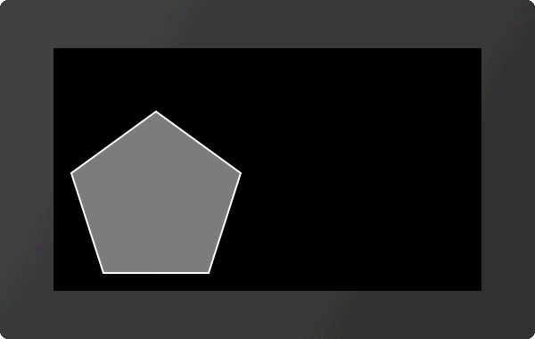
#GGP |
Obj-ID, DrawStyle-No, x, y, Anchor, Radius, Corners, FrameThickness(0), Angle(0) |
The command places a regular polygon with the Anchor and the given number of Corners at the position x, y. With the DrawStyle the appearance of the n-corner is determined (DrawStyle-No.). This is explained in more detail in the DrawStyle subsection. The Radius determines the size of the figure. It is also possible to determine a FrameThickness. Rotation around the anchor (Angle) can also be set. If anchor = 0, the construction point is used.
|
... #GGP 1,1,20,20,7,100,5 ... |
#GGS |
Obj-ID, DrawStyle-No, x, y, Anchor, Radius1, Radius2, Tip, FrameThickness(0), Angle(0) |
The command places a star with the Anchor at the position x, y. The appearance of the star is determined with the DrawStyle (DrawStyle-No.). This is explained in more detail in the DrawStyle subsection. The first tip is set to Radius1 above the center point. Then the connection to Radius2 is made then back to Radius1 etc. until the number of Tips is reached. It is also possible to determine a FrameThickness. Rotation around the anchor (Angle) can also be set. If anchor = 0, the construction point is used.
|
... #GGS 1,1,20,20,7,100,50,7 ... |

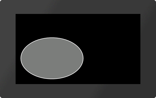
#GET |
Obj-ID, DrawStyle-No, x, y, Anchor, RadiusX, RadiusY(=RadiusX), FrameThickness(0), Winkel(0) |
The command places an ellipse with the Anchor and the RadiusX at the position x, y. The appearance of the circle is determined with the DrawStyle (DrawStyle-No.). This is explained in more detail in the DrawStyle subsection. If no RadiusY is specified, it is set to RadiusX (circle). It is also possible to determine a FrameThickness. Rotation around the anchor (Angle) can also be set.
|
... #GET 1,1,20,20,7,120,80 ... |
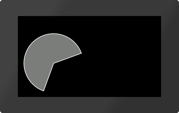
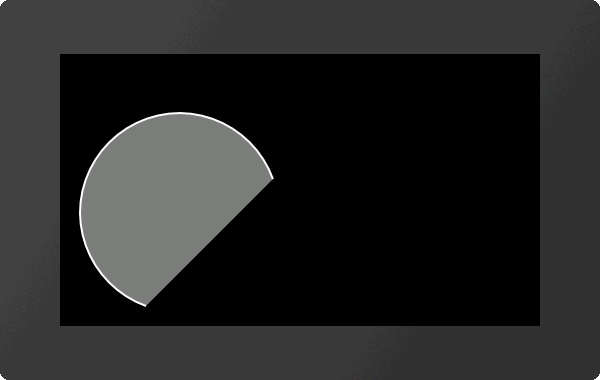
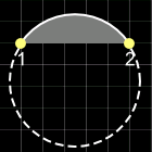
Place circular sector/piece of cake
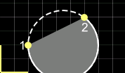
#GEP |
Obj-ID, DrawStyle-No, x, y, Anchor, RadiusX, RadiusY, StartAngle, EndAngle, Winkel(0) |
The command places a circle sector / piece of cake with the Anchor, the RadiusX and the RadiusY at the position x, y. Start-/EndAngles indicate the size of the piece. With the DrawStyle the appearance of the circle sector is determined (DrawStyle-No.). This is explained in more detail in the DrawStyle subsection. If no RadiusY is specified, it is set to RadiusX (circle). Rotation around the anchor (Angle) can also be set.
|
... #GEP 1,1,20,20,7,100,100,20,250 ... |
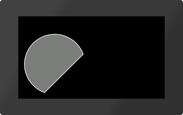
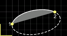
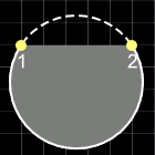
#GES |
Obj-ID, DrawStyle-No, x, y, Anchor, RadiusX, RadiusY, StartAngle, EndAngle, Winkel(0) |
The command places a segment of a circle with the Anchor, the RadiusX and the RadiusY at the position x, y. Start-/ EndAngles indicate the size of the piece. The appearance of the circle segment is determined with the DrawStyle (DrawStyle-No.). This is explained in more detail in the DrawStyle subsection. If no RadiusY is specified, it is set to RadiusX (circle). Rotation around the anchor (Angle) can also be set.
|
... #GES 1,1,20,20,7,100,100,20,250 ... |
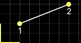
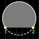
#GEA |
Obj-ID, DrawStyle-No, x, y, Anchor, RadiusX, RadiusY, StartAngle, EndAngle, Border(0), Angle(0) |
The command places an arc with the Anchor, the RadiusX and the RadiusY at the position x, y. Start-/ EndAngles indicate the size of the piece. The appearance of the circular arc is determined with the DrawStyle (DrawStyle-No.). This is explained in more detail in the DrawStyle subsection. If no RadiusY is specified, it is set to RadiusX (circle). It is also possible to determine a frame thickness. Rotation around the anchor (Angle) can also be set.
|
... #GEA 1,1,20,20,7,100,100,20,250 ... |
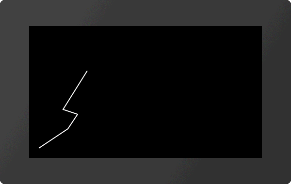
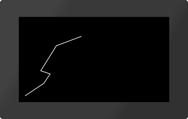
#GPL |
Obj-ID, DrawStyle-No, x1, y1, x2, y2, ... xn, yn |
The command draws a polyline with the coordinates [x1, y1], [x2, y2], ..., [xn, yn]. The appearance of the polyline is determined with the DrawStyle (DrawStyle-No.). This is explained in more detail in the DrawStyle subsection.
|
... #GPL 1,1,20,20,80,60,100,90,70,100,120,180 ... |
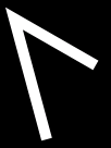
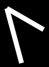
Polylinie settings (from V1.5)
#GPO |
Obj-DI, Fast drawing |
This command enables / disables a routine for accelerated drawing (Fast drawing) of polylines. However, the edges of the lines are ignored and only single lines are drawn.
Fast drawing |
|
inactive (0) |
active (1) |
|
|
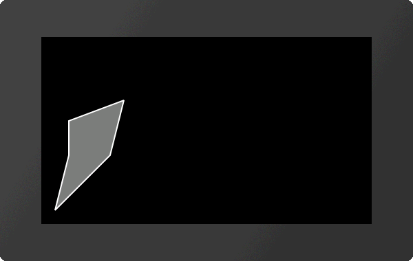
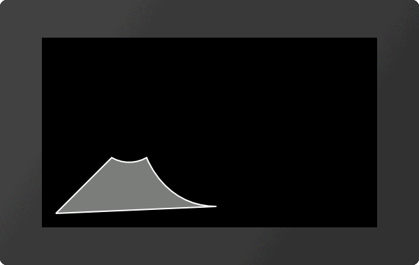
#GPF |
Obj-ID, DrawStyle-No, x1, y1, x2, y2, ... xn, yn |
The command draws a filled polygon with the coordinates [x1, y1], [x2, y2], ..., [xn, yn]. The appearance of the polygon is determined with the DrawStyle (DrawStyle-No.). This is explained in more detail in the DrawStyle subsection. From the last given point the shape is automatically closed.
|
... #GPF 1,1,20,20,100,100,120,180, 40,150,40,100 ... |
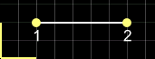
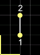
Add points to polyline/polygon
#GPA |
Obj-ID, x1, y1, x2, y2, ... xn, yn |
The command adds coordinates [x1, y1], [x2, y2], ..., [xn, yn] at the end of a polyline or polygon. In the case of a polygon, the figure is closed automatically.
|
... #GPL 1,1,20,20,80,60,100,90,70,100,120,180 #GPA 1,200,210 ... |
#GPP |
Obj-ID, DrawStyle-No, x, y, Segment1, ..., SegmentN |
The command draws a path with the starting position x, y. The appearance of the polygon is determined with the DrawStyle (DrawStyle-No.). This is explained in more detail in the DrawStyle subsection. The individual segments follow. If the segment commands are capitalized (e.g.? H,? L, ...), absolute coordinates are used - for lower case letters (e.g.? H,? L, ...) relative coordinates. The following segment commands are available:
Segment |
Beispiel |
||
Horizontal line |
?H x |
|
?H 140 |
Vertical line |
?V y |
|
?V 80 |
Line |
?L x, y |
|
?L 140,80 |
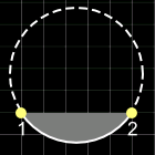
Arc |
?C Arc, Radius, x, y |
|
?C 2,50,120,80 |
Elliptical arc |
?E Arc,Radius-x, Radius-y, Angle, x, y |
|
?E 1,80,40,10,180,80 |
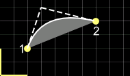
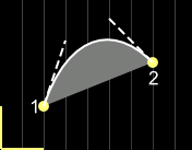
Quadratic Bézier-curve |
?Q c1x, c1y, x, y |
|
?Q 60,100,140,80 |
Smooth quadratic Bézier-curve (the previous control point is mirrored) |
?R x, y |
|
?R 220,100 |
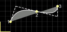
Cubic Bézier-curve |
?S c1x, c1y, c2x, c2y, x, y |
|
?S 60,100,100,120,140,80 |
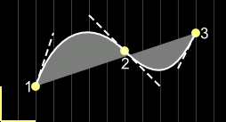
Smooth cubic Bézier-curve (the previous control point is mirrored) |
?T c2x, c2y, x, y |
|
?T 200,60,220,100 |
Close path |
?Z |
||
Jump to new start position (sub-path) |
?M x, y |
||
In the case of a circular arc or elliptical circular arc, the circular arc must be specified more precisely:
|
... #GPP 1,1,20,20,?L100,100,?C0,50,150,100,?T175,30,250,30,?Z ... |
Add sub-path to path (from V1.1)
#GPS |
Obj-ID, Segment1, ..., SegmentN |
Additional Segments will be added to an existing path.
Place path (segments as string) (from V1.2)
#GPT |
Obj-ID, DrawStyle-No, x, y, "Segment1, ..., SegmentN" |
The command does the same as #GPP. However, the individual segments are passed as a string.
Define marker for path (from V1.5)
#GPM |
Obj.-ID, Marker Obj-ID |
Any existing object (Marker Obj.-ID) can be used as a marker for a path (Obj-ID).
|
... #GPM 1,2 ... |