Diagrams #D (from V1.5)
Command group to display line graphs. |
|

Coordinate system
Place coordinate system (Diagram Coordinate Place) |
Obj-ID, x, y, Anchor, Image-No., Offset-x, Offset-y, Width, Height, Step-x, Step-y |
|
Place text form coordinate system (Diagram Coordinate Text) |
Obj-ID, Axis-No., Textstyle-No.,Formatted string, x, y, Anchor, Angle, Alignment, Start value, Step |
|
Set start values for coordinate system (Diagram Coordinate Set) |
Obj-ID, Axis-No., Start value |
|
Set visibility for labeling of coordinate system (Diagram Coordinate Visible) |
Obj-ID, Axis-No., Visibility, Labeling-No. |
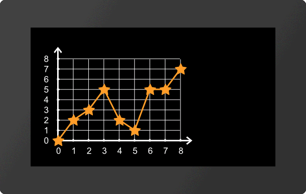
Lines
Define line (Diagram Line Place) |
Obj-ID, Line-No., DrawStyle, Connection type, y-Axis-No., y-Array-ID, x-Axis-No., x-Array-ID(negative)/Values per step |
|
Define marker for line (Diagram Line Marker) |
Obj-ID, Line-No., Visibility, Marker Obj-ID |
|
Define scaling factor for line (Diagram Line Calculate) |
Obj-ID, Line-No., Factor-y, Offset-y, Factor-x, Offset-x |
|
Define visibility for line (Diagram Line Visible) |
Obj.ID, Visibility, Line-Nr., ...,Line-Nr [Nr+1] |
Settings Diagram
Set touch functionality (Diagram Define Touch) |
Obj-ID,Move, Scale |
|
Change window size of coordinate system (absolute) (Diagram Window Absolut) |
Obj-ID, x., y, Scale-x(0), Scale-y(0) |
|
Change window size of coordinate system (relative) (Diagram Window Relativ) |
Obj-ID, x., y, Scale-x(0), Scale-y(0) |
|
Change zoom of coordinate system (Diagram Window Zoom) |
Obj-ID, Scale-x, Scale-y(0) |
|
Change start value of coordinate system (Diagram Window Value) |
Obj-ID, Axis-No., Value, Scale(0) |
|
Change Auto Scroll from Coordinate System (Diagram Window Scroll) |
Obj-ID, Scroll, Step, Update Labeling |
All commands marked with * are used by the Diagram Editor (part of uniTFT Designer) to define diagrams. They are not explained in detail below.
|
|

Coordinate system
The diagram editor (part of uniTFT Designer) is used to place and set the coordinate system.
Set visibility for labeling of coordinate system
#DCV |
Obj-ID, Axis-No., Visibility, Labeling-No. |
This command sets the visibility of individual axis labels for the diagram with the Obj.ID. The axis number can be found in the diagram editor. The Index parameter (1-...) specifies for which text in the axis labelling the visibility should be changed.
Visibility |
|
0 |
Invisible |
1 |
Visible |
|
... #DCV 1,1,0,4 /**x-axis #DCV 1,2,0,6 /**y-axis ... |
Lines
The definition of lines and the assignment to an array is done by the Diagram Editor (part of the uniTFT Designer).
#DLM |
Obj-ID, Line-No., Visibility, Marker Obj-ID |
This command sets the visibility of markers (Marker Obj-ID) for the diagram with the Obj-ID. Any existing object can be used as a marker. The line number can be found in the diagram editor.
Visibility |
|
0 |
Invisible |
1 |
At the end |
2 |
All |
4 |
Min/Max |
|
... #DLM 1,1,2,2 ... |
Define scaling factor for line
#DLC |
Obj-ID, Line-No., Factor-y, Offset-y, Factor-x, Offset-x |
The command sets the scaling factor of the line (Line no.) for the diagram with the Obj-ID. The line no. can be found in the diagram editor. This allows the value range of the raw data (e.g. analog input) to be adapted to the output values (Factor-y / Offset-y). If an array is also used for the x-axis, these values can also be scaled accordingly (Factor-x / Offset-x)
|
... #DLC 1,1,0.5,2,1,0 ... |
#DLV |
Obj.ID, Visibility, Line-Nr., ...,Line-Nr [Nr+1] |
The command sets the visibility of the line (Line No.) for the diagram with the Obj-ID.
Visibility |
|
0 |
Invisible |
1 |
Visible |
Settings Diagram
The definition of lines and the assignment to an array is done by the Diagram Editor (part of the uniTFT Designer).
#DTD |
Obj-ID,Move, Scale |
The command sets the touch functionality for the diagram with the Obj-ID. For both movement and scaling it can be specified whether and in which direction touch events are evaluated.
Move |
|
0 |
No movement |
1 |
only in x-direction |
2 |
only in y-direction |
3 |
in x- and y-direction |
Scale |
|
0 |
No scaling |
1 |
only in x-direction |
2 |
only in y-direction |
3 |
in x- and y-direction |
Change window size of coordinate system (absolute)
#DWA |
Obj-ID, x., y, Scale-x(0), Scale-y(0) |
The command changes the window size of the coordinate system of the diagram with the Obj-ID absolute. The displacement in x and y direction is given in pixels and the scaling in percent.
|
... #DWA 1,30,0,200,0 ... |
Change window size of coordinate system (relative)
#DWR |
Obj-ID, x., y, Scale-x(0), Scale-y(0) |
The command changes the window size of the coordinate system of the diagram with the Obj-ID relative. The displacement in x and y direction is given in pixels and the scaling in percent.
|
... #DWR 1,-90,0,50,0 ... |
Change zoom of coordinate system
#DWZ |
Obj-ID, Scale-x, Scale-y(0) |
The command changes the zoom of the coordinate system of the diagram with the Obj-ID. The scaling is given in percent.
|
... #DWZ 1,50,200 ... |
Change start value of coordinate system
#DWV |
Obj-ID, Axis-No., Value, Scale(0) |
The command changes the start value of the coordinate system of the diagram with the Obj-ID. The axis number can be found in the diagram editor.
|
... #DWV 1,1,2 ... |
Change Auto Scroll from Coordinate System
#DWS |
Obj-ID, Scroll, Step, Update Labeling |
The command changes the auto-scroll behavior of the coordinate system of the diagram with the Obj-ID. The Scroll parameter enables or disables the automatic scrolling. The step size specifies how far back the coordinate system is moved at the end. The value is a factor (float) which is multiplied by the step size of the coordinate system. With the parameter Update labeling you can specify whether the values of the labeling should change when scrolling.
Scroll |
|
0 |
Deactivate |
1 |
Activate |
Update labeling |
|
0 |
Do not adjust labeling |
1 |
Adjust labeling |