SPI
The Serial Peripheral Interface is a bus system for serial synchronous data transfer.
The EA uniTFT provides 2 separate interfaces SPI: the Slave interface (pins 4-7) is used to communicate with the display. All data sent to the display are interpreted as a command (with and w./o. Small-/Short-Protocol). Would you like to send and receive any data via SPI to other devices like temperature sensor, then you have to use the Master lines (pins 47-50). Those are handled via #H commands.
The SPI is working with 4 lines:
- MOSI (Master Out → Slave In) or SDO (Serial Data Out) or DO
- MISO (Master In ← Slave Out) or SDI (Serial Data In) or DI
- SCK (Serial Clock) - Shift clock
- SS (Slave Select → Addressing) or CS (Chip Select)
SPI works with a bidirectional transmission principle, meaning that data is exchanged between the connected devices at the same time. The communication is controlled by the master using the SCK line.
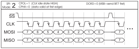
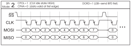
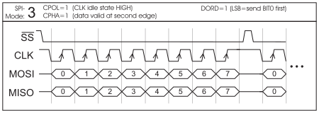
The protocol for data transfer is not defined in SPI, therefore there are different configuration possibilities, which are defined by the parameters Clock Polarity, Clock Phase and Data Order. The default setting is SPI mode 3 with DORD = 0. The commands #XCS and #HSP (master interface) ) set the mode 0..3. Alternatively the command can be stored directly into the boot file <start.emc>.
Mode |
CPOL |
CPHA |
DORD (0) - MSB First |
DORD (1) - LSB First |
0 |
0 |
0 |
*1
|
*1
|
1 |
0 |
1 |
|
|
2 |
1 |
0 |
*1
|
*1
|
3 |
1 |
1 |
|
|
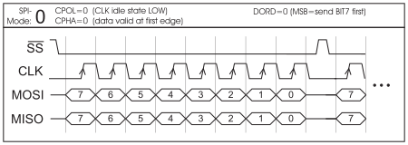
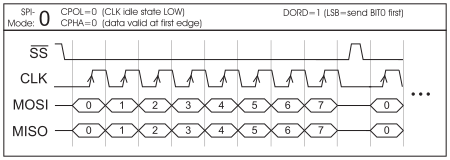
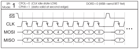
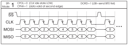
You may check the current settings in Boot menu.
The maximum clock frequency is 1 MHz. The module needs some time to prepare data for transfer. That means a wait cycle (no activity on the SCK-line) of at least 50 μs is required before reading data.
*1 ATTENTION:
As a slave in mode 0 and mode 2, the EA uniTFT requires a negation of the SS signal after each byte. Permanent activation is not permitted.