HMIDesigner
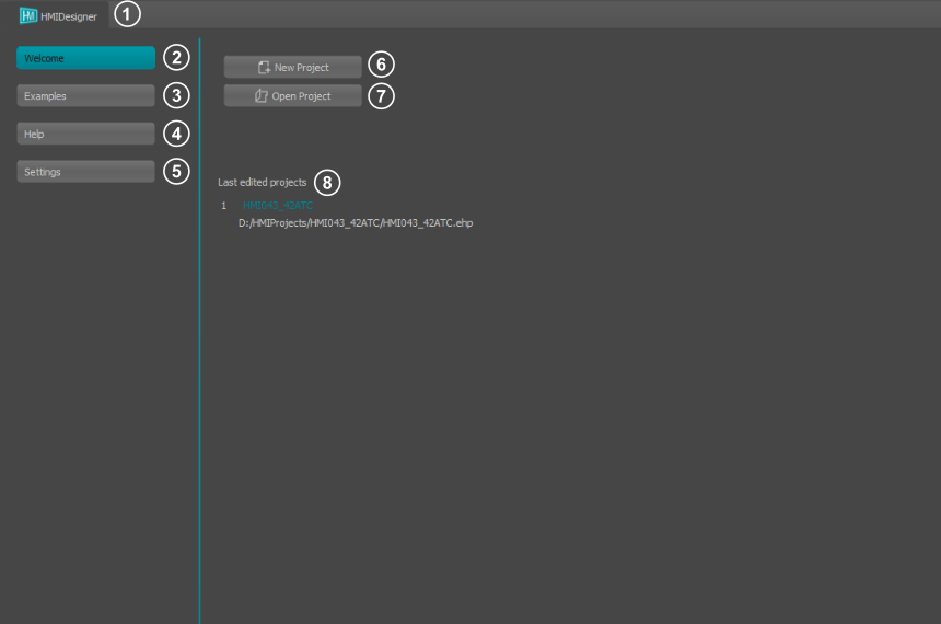
When you start HMIDesigner, the WelcomePage appears first. Here you can create new projects or open existing ones. You can also access the help file and sample projects.
|
- Switches between the Welcome Page and the Editor Window
- Shows the WelcomePage
- Example projects for the HMIDesigner
- Displays the help files for the HMI commands
- HMIDesigner settings
- Creates a new project
- Opens a project
- List of recently used projects
|
Create new project
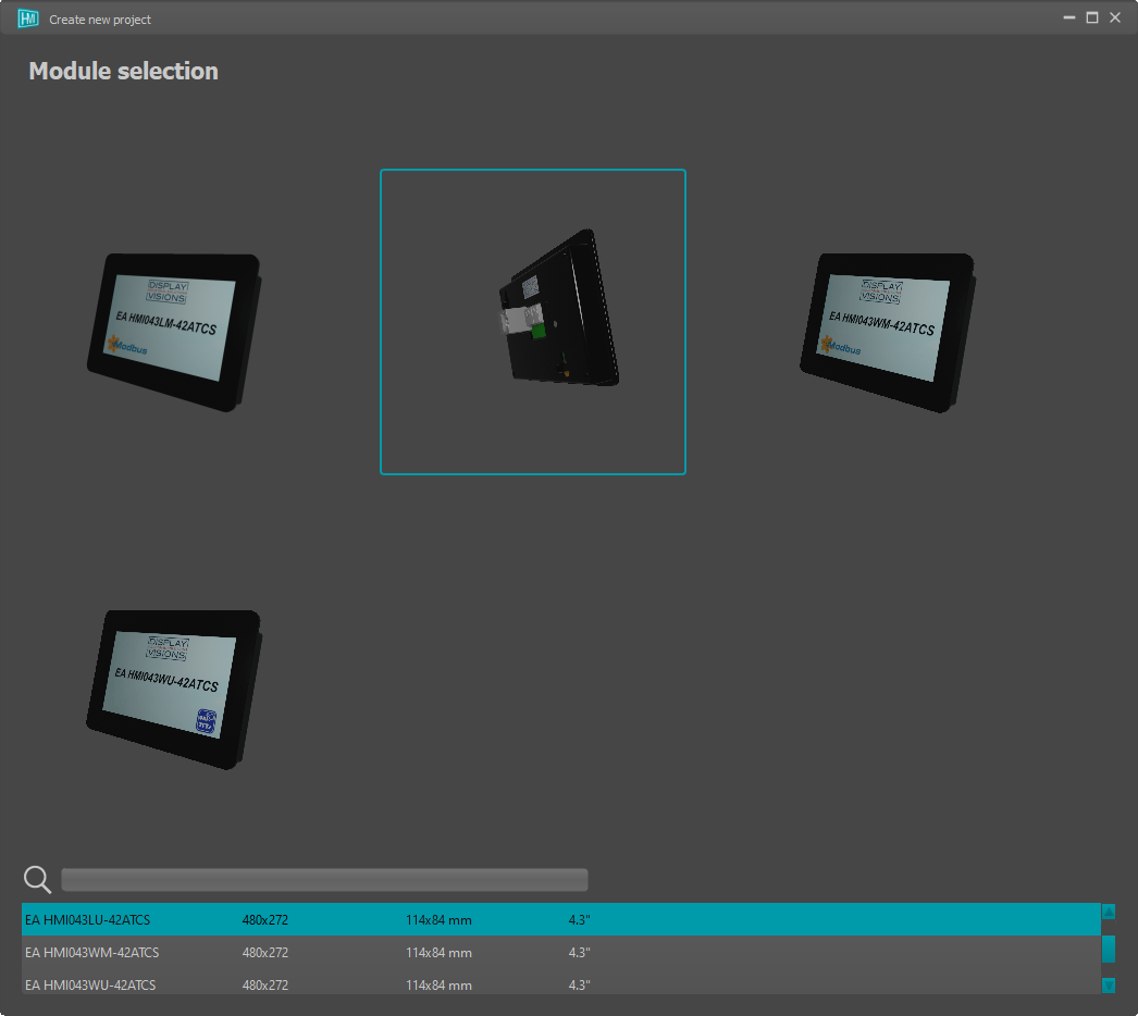
When creating a new project, you must select the module. On the bottom of the window there is table with mechanical information as well as a search field.
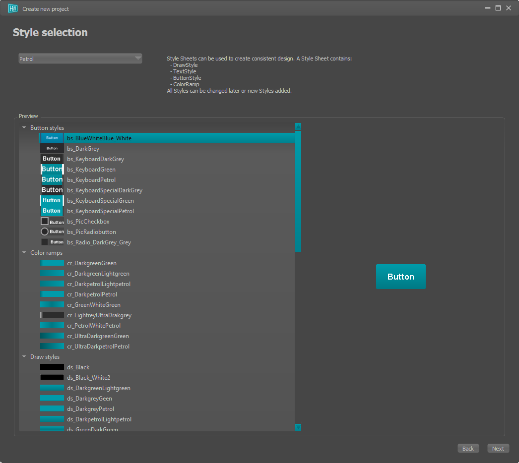
In a second step, you select a style template for the display. There is a default selection of styles. However, you can also create your own stylesheets, which can later be selected from the list. In addition, all styles can be changed and new ones created in each project.
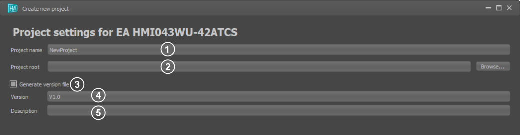
In the last step, you assign a project name and other settings for the project
|
- Project name
- Project directory
- Activation of the version management
- Version name
- Version description
|
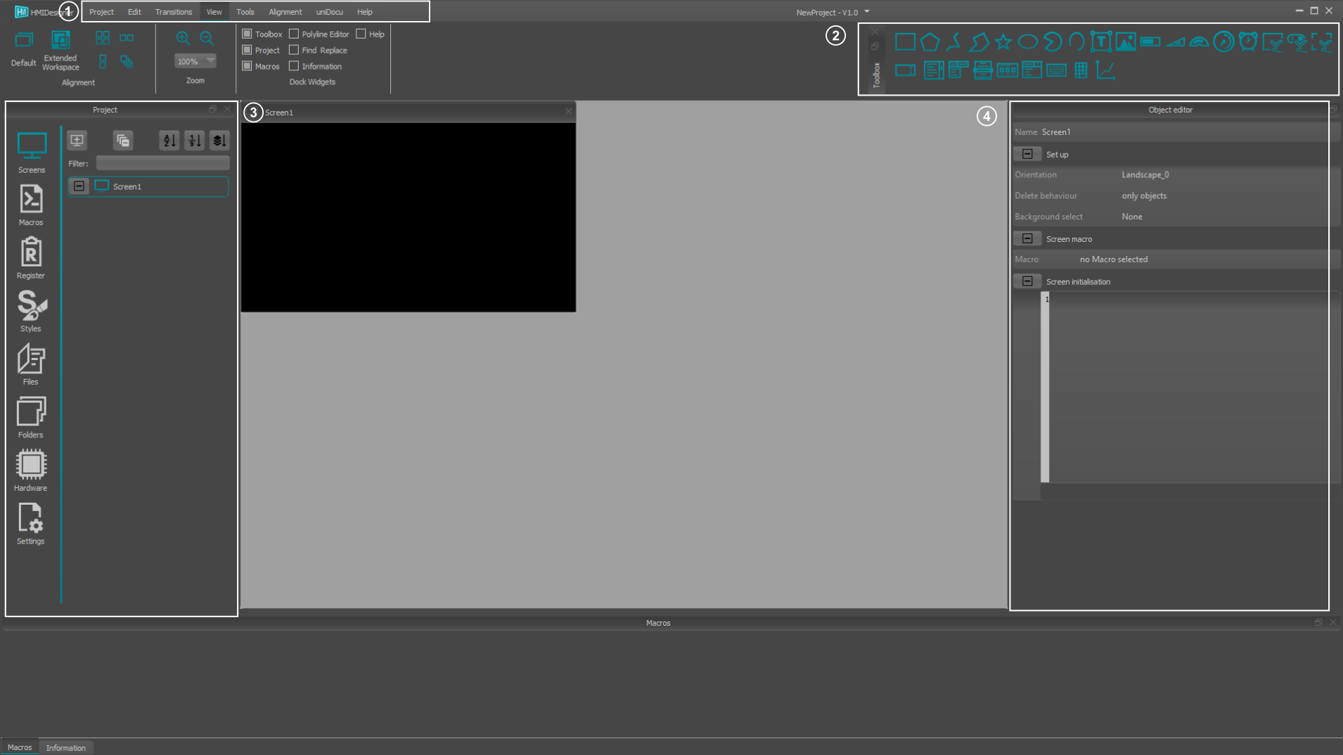
HMI Editor window
|
- Ribbon tab
- Toolbox
- Project elements
- Object editor
|
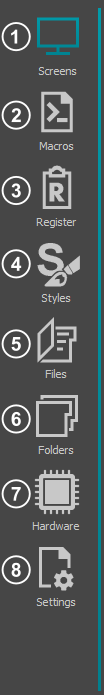
Project Elements
|
- Overview of all screens and their objects
- Creating and editing macros
- Creating and editing registers
- Create and change styles
- Embedded external files
- Embedded external folders
- Hardware settings
- Project settings
|
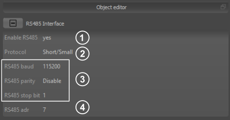
Hardware settings: Connection RS485
|
- Enable RS485: Set to 'yes' to active RS485. Other interfaces are deactivated automatically
- Protocol: Read only. Protocol is predefined. Refer to module selection guide.
- RS485 baudrate, parity, stopbit: Set the hardware RS485 settings
- RS485 adr: Sets the RS485 slave adress. In modbus slave mode it is the modbus slave adress.
|
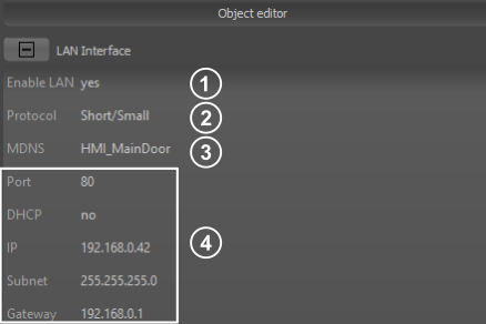
Hardware settings: Connection LAN
|
- Enable LAN: Set to 'yes' to active LAN. Other interfaces are deactivated automatically
- Protocol: Read only. Protocol is predefined. Refer to module selection guide.
- MDNS: SetMulticast DNS name to find HMI module easily in the network, especially with turned on DHCP mode
- Network settings: Enable/Disable DHCP and set IP address. Choose a port that is not blocked by any firewalls.
|
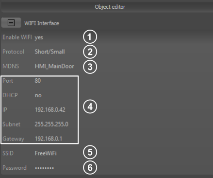
Hardware settings: Connection WiFi
|
- Enable LAN: Set to 'yes' to active LAN. Other interfaces are deactivated automatically
- Protocol: Read only. Protocol is predefined. Refer to module selection guide.
- MDNS: SetMulticast DNS name to find HMI module easily in the network, especially with turned on DHCP mode
- Network settings: Enable/Disable DHCP and set IP address. Choose a port that is not blocked by any firewalls.
- SSID: Service set identifier for wireless network
- Password: Suiting password for selected WiFi.
|
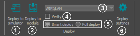
Deployment
|
- Deploy to simulator: Transfers the project to the simulator
- Deploy to module: Transfers the project to the module
- Port: Set the connection port (COM port or WIFI/LAN)
- Verify: Enable/Disable project verify after deployment
- Deploy strategy: Smart deploy: transfers only modified files; Full deploy: transfers the whole project
- Deploy settings: Sets the transmission parameters (e.g. baudrate, IP address, ...)
|
|
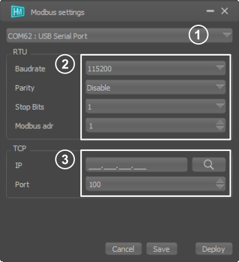
- Port: Set the connection port (COM port or WIFI/LAN)
- RTU settings: Set RS485 baudrate, parity and stop bits as well as the Modbus address.
- TCP settings: Set IP address and port. It is possible to search for the IP address
|
Register Settings
Under the menu item Register, registers, string registers and arrays can be created and edited. You can also select whether the individual registers should be synchronised with all connected modules.
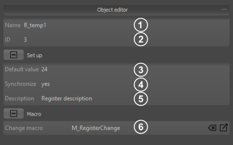
Numerical and String registers
|
- Name: An individual name can be assigned to each register. The value can then be accessed directly with the register name (R_temp1).
- Id: A unique ID is assigned to each register. Many commands require this Id to address the correct register. In PLCDesigner you can also reach the Id with the beautified name ID{R_temp1}
- Default value numeric: Value the register has after power on. By default, the register is created as an integer register (signed 32Bit). If a floating point number is specified as default value, a float register (23 Bit Mantissa, 8 Bit Exponent, 1 Bit signed) is created.
Default value string: Value the register has after power on. Strings with a maximum of 200 characters are allowed.
- Synchronize register: Read only information. This value is applicable for Modbus, only. It is automatically set to true, if a modbus register is mapped to the internal register
- Description: A description can be added to each register.
- Change macro: The macro is called every time the register value changes.
|
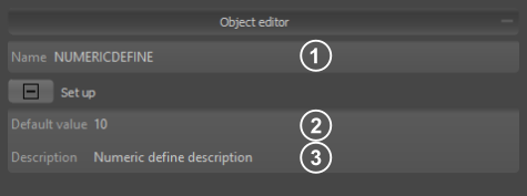
Numerical and String defines
|
- Name: The name can be used to access the defines in the macros.
- Default value: Value of the numerical or string define.
- Description: A description can be added to each define.
|
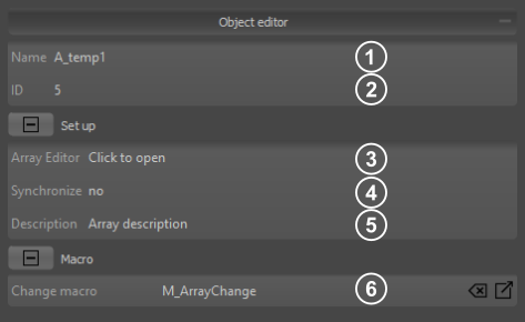
Arrays and String arrays
|
- Name: An individual name can be assigned to each array. The value can then be accessed directly with the array name and array index starting with 0 (A_temp1(0)).
- Id: A unique ID is assigned to each array. Many commands require this Id to address the correct array. In PLCDesigner you can also reach the Id with the beautified name ID{A_temp1}
- Array Editor: Opens the array Editor
- Synchronize array: If synchronisation is selected, the whole array is automatically shared with all connected modules in the network.
- Description: A description can be added to each array.
- Change macro: The macro is called every time a array value changes.
|
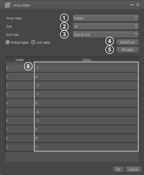
Array editor
|
- Array type: Selection of the array typ (integer or float). This option is only available for numeric arrays.
- Size: Specifies the size (number of entries) of the array.
- Array end typ: This parameter defines whether the automatic filling of the array is aborted at the end or the write pointer automatically wraps around and overwrites the values again from the beginning.
- Import option: It is possible to fill the array with values from a CSV file. You can also choose whether the current values from the file should be entered permanently in the PLCDesigner or whether the file should be linked ( data changes in the file are then always automatically adopted in the PLCDesigner).
- Fill array: There are different possibilities to fill the default values of the array automatically (e.g. with zero, with random values).
- Default values: Values the array has after power on
|
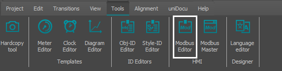
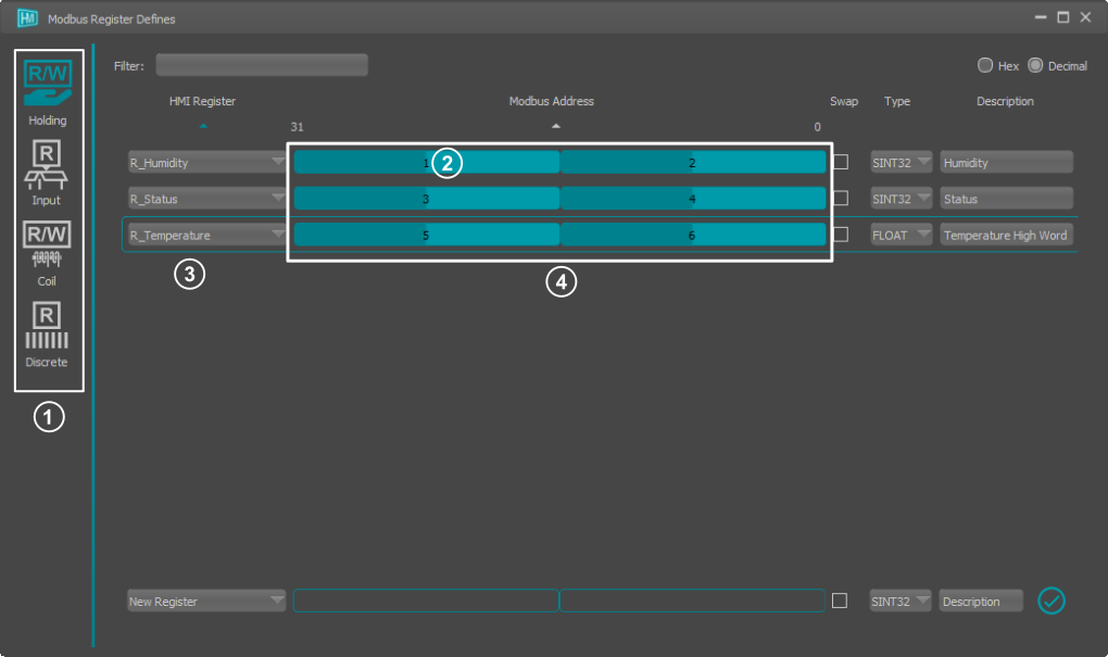
Modbus Editor (EA HMI043xM only)
The Modbus Editor is used to map Modbus Registers (16bit) to internal module Registers (32bit), accessable with commands like #VRI. A maximum of 256 modbus registers can be used.
|
- Modbus data model: Switch between the four primary tables.
- Modbus Register: Register address inside primary table.
- HMI Register: Internal module register (HMI Register). This register can be accessed directly in macros.
- Register mapping: Use drag 'n' drop to map Bytes / Bits to specific positions in HMI Registers
|
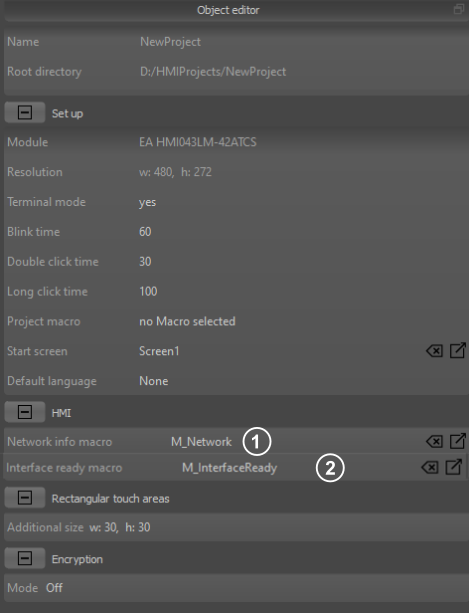
Project Settings
|
- Network info macro: The macro is started when changes occured regarding the network connection of the module. The calculation command plcW() changes its' output.
- Interface ready macro: The macro is started when HMI interface has bootet completly. Commands like version(1) give proper feedback.
|